MPO Connectors Are Essential in Data Centers
Multi-fiber push on connectors, or MPOs for short, are fiber connectors incorporating multiple optical fibers. These connectors are found primarily in data center environments for consolidating multiple fibers in backbone cabling and supporting parallel optics applications that transmit and receive signals over multiple fibers to achieve higher speeds.
Contents
- What Is an MPO Connector?
- MPO Certifications and Standards
- MPO Applications
- Very Small Form Factor MPOs
- Cleaning and Inspecting MPOs
- MPO Polarity
- How to Test MPO Cable
- Keep Learning
What Is an MPO Connector?
Originally introduced for use with multi-fiber ribbon cable, MPO connectors feature a linear array of fibers in a single ferrule. They are defined as an array connector with more than 2 fibers; they are available with 8, 12, 16, or 24 fibers for common data center applications. Higher fiber counts are available, such as 32, 48, 60, or even 72 fibers; these are typically used for specialty super high-density multi-fiber arrays in large scale optical switches. MPOs with 8 to 16 fibers feature one row of fibers, while higher-density MPOs with 24 or more fibers feature multiple rows.
MPO connectors come in male (with pins) and female (without pins) for proper mating to avoid damaging the fibers. Note that all MPO equipment ports are male, so any MPO cable that connects to equipment must have a female connector. MPO connectors are also keyed and feature a white dot to denote the first fiber position, which helps ensure proper polarity where each transmit fiber corresponds to the right receive fiber. The key location varies across different MPO connectors; 8-, 12-, and 24-fiber MPOs have the key in the center, while 16- and 32-fiber MPO connectors have the key offset to the left.
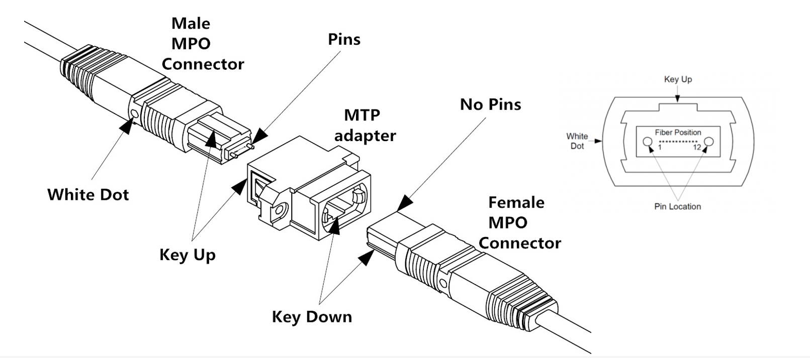
MPO connector structure
You may also see the term “MTP connector” used interchangeably with MPO connector. The term MTP is a registered trademark of the MPO connector offered by US Conec. The MTP connector is fully compliant with MPO standards and is described by US Conec as an MPO that has been engineered to very tight tolerances for improved alignment, durability, and performance. For the purposes of this discussion, we will refer to only MPO connectors since MTPs are technically MPO connectors.
MPO Certification and Standards
As with other standards-based connector interfaces, manufacturers of MPO connectors must comply with intermateability standards. For MPO connectors, these include IEC 61754-7 and EIA/TIA-604-5 (FOCIS 5) standards that specify the physical attributes of the connector, such as pin and guide hole dimensions for male and female interfaces. These standards ensure that any compliant plugs and adapters can be intermated and meet a certain level of performance.
In addition to intermateability, MPO connectors also must meet specific end face geometry parameters defined by the IEC PAS 61755-3-31 fiber optical interface standard. These include angle of polish, fiber protrusion height, and maximum fiber height differential across all fibers in the array and for adjacent fibers. The overall performance of the connector depends on precisely controlling these mechanical characteristics. For example, if the fiber height differential is exceeded and fibers in the array are not of equal height, some fibers will not achieve proper mating. This can significantly impact insertion loss and return loss.
MPO Applications
MPO connectors are used in duplex fiber applications throughout the data center as a way to deploy pre-terminated plug-and-play backbone trunk cables between active equipment. MPO-terminated trunk cables used in duplex backbone links take up less pathway space, ease cable management, and offer faster deployment compared to using individual duplex cables. When used for duplex backbone applications, trunk cables with 12-fiber or 24-fiber MPO connectors on both ends form the permanent backbone link, and then transition to either 6 or 12 duplex fiber connectors at patch panels via either MPO-to-LC cassettes or MPO-to-LC hybrid patch cords.
MPO connectors are also the de facto interface for parallel fiber optic applications that transmit and receive over multiple fibers as a means to increase transmission speed. One of the first parallel applications that called for MPOs was 40 Gig and 100 Gig multimode applications (40GBASE-SR4 and 100GBASE-SR4), which use 8 fibers with 4 transmitting and 4 receiving at either 10 Gbps or 25 Gbps per lane. Note that while these 8-fiber data center applications are best supported by 8-fiber MPO connectors, 12-fiber MPOs connectors can be used with the middle 4 fiber positions unused.
With advancements in encoding technology that now enable 50 and 100 Gbps per lane, 8-fiber MPOs are also used for 200 and 400 Gbps parallel optic applications with 4 fibers transmitting and 4 receiving at either 50 or 100 Gbps. 800 Gig applications use 16-fiber MPOs, with 8 fibers transmitting and 8 receiving at 100 Gbps. 200 Gbps-per-lane technology can be used to support 800 Gig using 8-fiber MPOs with 4 fibers transmitting and 4 receiving at 200 Gbps, and 1.6 Terabit can used 16-fiber MPOs with 8 transmitting and 8 receiving at 200 Gbps. With speeds ever increasing, the MPO connector interface is here to stay.
Breakout cables with an MPO connector on one end and duplex connectors on the other end are ideal for breakout applications where one high-speed switch port connects to multiple lower-speed duplex switch or server ports. Breakout applications help reduce cost by maximizing switch port density and port utilization. For example, a single 100 Gig switch port with an 8-fiber MPO interface can connect to four 25 Gig servers.
Very Small Form Factor (VSFF) MPOs
With the first iteration of 800 Gig parallel fiber optic applications (and future 1.6 Terabit applications) set to use 16-fiber MPOs, leading connector manufacturers have introduced very small 16-fiber MPOs that offer nearly three times the density of traditional 16-fiber MPOs. This is critical for enabling higher switch port and patch panel densities to save space in high-performance computing environments. VSFF 16-fiber MPO connectors include the SN-MT from Senko and the MMC-16 from US Conec. To put the size difference into context, 216 SN-MT or MMC-16 connectors fit in the same space as 80 traditional 16-fiber MPO connectors.
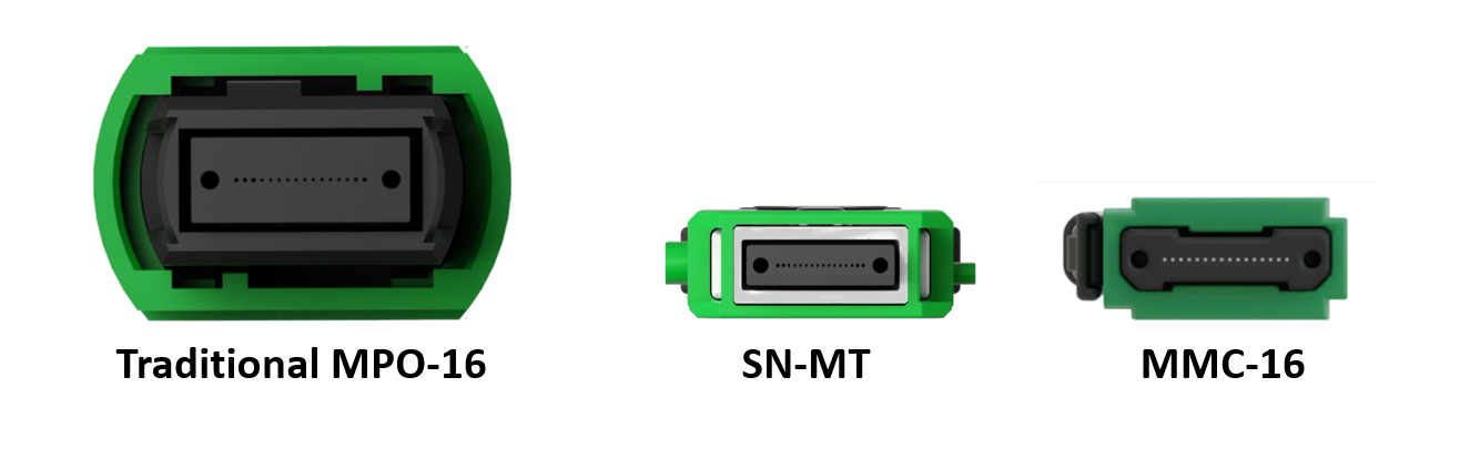
New VSFF 16-fiber MPO connectors are nearly one-third the size of traditional 16-fiber MPO connectors. They offer improved density in high-performance computing MPO connector structures. Source: Senko and US Conec.
Cleaning and Inspecting MPOs
Every fiber end face should be inspected and, if necessary, cleaned before connection, and MPO connectors are no different. In fact, cleaning and inspecting can be even more of a concern for MPO connectors due to their larger surface area. When cleaning these larger surface areas, contaminants can move from one fiber to another within the same array — and the larger the array, the higher the risk.
With a greater number of fibers, such as with 16- or 24-fiber MPO connectors, the height differential of fibers is more difficult to control. Even the slightest height variances across the fibers can increase the risk that not every fiber will be properly and equally cleaned. That’s why it’s critical to inspect, and, if needed, clean and inspect again.
When it comes to inspecting fiber end faces, IEC 61300-3-35 “Basic Test and Measurement Procedures Standard for Fiber Optic Interconnecting Devices and Passive Components” contains specific cleanliness grading criteria to assess pass or fail certification for inspection of a fiber end face, removing the human subjectivity factor and avoiding any disputes. For various connector types and fiber size, IEC 61300-3-35 certifies the cleanliness of a fiber end face based on the number and size of scratches and defects found in each region of the end face, including the core, cladding, adhesive layer, and contact zones.
When cleaning and inspecting MPO connectors, using a cleaner and inspection equipment that are specifically designed for MPOs saves time and improves accuracy. The Fluke Networks FI-3000 FiberInspector Ultra inspects MPO connectors and provides an automated PASS/FAIL result compliant with IEC 61300-3-35. We also offer MPO Quick Clean™ Fiber Optic Cleaning Kits to make it easier than ever to ensure that your MPO connector end faces are clean.
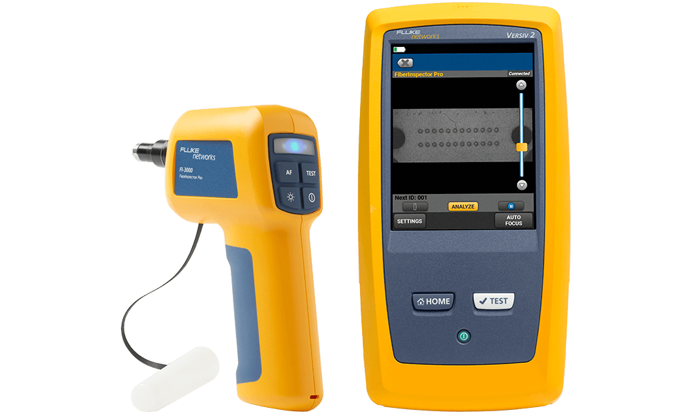
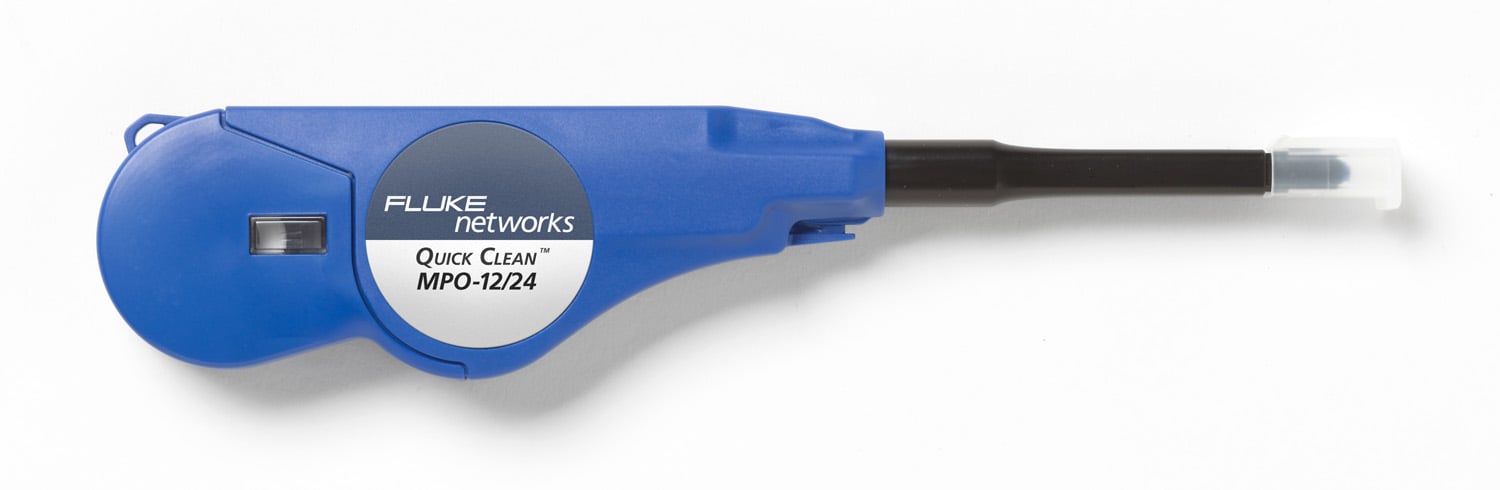
The FI-3000 FiberInspector Ultra (left) inspects MPO connectors and provides automated PASS/FAIL result per IEC 61300-3-35 procedures. An MPO Quick Clean Cleaner (right) is specifically designed for cleaning MPO connectors.
MPO Polarity
For fiber links to properly send data, the transmit signal (Tx) at one end of the cable must match the corresponding receiver (Rx) at the other end. The purpose of any polarity scheme is to ensure this continuous connection — which becomes a bit more complex when you’re dealing with multi-fiber MPO components.
For MPO cables, industry standards identify 3 different polarity methods:
- • Method A uses Type A straight-through MPO trunk cables with a key up connector on one end and a key down connector on the other end, so that the fiber located in Position 1 arrives at Position 1 at the other end. When using Method A for duplex applications, making the transceiver-receiver flip is required in a patch cord at one end.
- • Method B uses key up connectors on both ends to achieve the transceiver-receiver flip so that the fiber located in Position 1 arrives at Position 12 at the opposite end, the fiber located in Position 2 arrives at Position 11 at the opposite end, and so on. For duplex applications, Method B uses straight A-B patch cords on both ends.
- • Method C uses a key up connector on one end and a key down connector on the other end like Method A, but the flip happens within the cable itself, where each pair of fibers is flipped so that the fiber in Position 1 arrivers at Position 2 at the opposite end and the fiber in Position 2 arrives at Position 1. While this method works well when using MPO trunk cables for backbone connections in duplex applications, it does not support parallel fiber applications and is therefore not recommended.
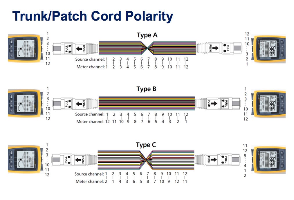
The 3 different polarity methods used for MPO cables.
With 3 different polarity methods, and the need to use the correct type of patch cords for each, deployment mistakes can be common. The Fluke Networks MultiFiber™ Pro allows you to test individual patch cords, permanent links, and channels easily for correct polarity.
How to Test MPO Cable
Just like any fiber link in the data center, those that use MPO connectors still need to be tested to ensure that they remain within insertion loss budgets. This is especially true for higher-speed 40, 100, 200, and 400 Gig parallel fiber optic applications that require the use of MPOs. Since these applications have much lower loss budgets, it’s important to maintain the highest testing accuracy possible.
Before the MultiFiber Pro tester with on-board MPO connectors was available, MPO-based fiber links were tested with a traditional duplex fiber tester. It was an extremely time-consuming task, requiring use of MPO-to-LC fan-out cords that separate the multiple fibers into single fiber channels, and verification of test reference cords before connecting each of the fiber pairs to be tested on both ends. This complex testing also led to greater inconsistencies and made it more difficult to keep all the fibers clean during the process.
With its ability to scan all fibers of an MPO connector simultaneously, a tester like the MultiFiber Pro with an on-board MPO connector eliminates complexity and tests 90% faster than using a duplex tester. In fact, the IEC TR 61282-15 Ed1 design guide “Cable plant and link — Testing multi-fibre optic cable plant terminated with MPO connectors” requires that testers must have an MPO interface when testing these systems.
Keep Learning
- • Fiber Contamination, Cleaning, and Inspection: An Introduction
- • Why an MPO Inspection Camera? | An Interview with the Product Manager
- • Fiber Polarity Basics
- • The Road to 200 & 400 Gig is Already Paved (and Traveled)
- • The Rise of the Hyperscale Data Center
- • Data Center Cabling
- • Testing Cabling with MPO Connectors – What’s New?
- • Benefits of Using 8-Fiber Plug and Play MPO Solutions
- • Rely on Duplex Tester for MPO Cable Certification
Related Products

FI-3000 / FI2-7300 FiberInspector™ Ultra Camera
FI-7000 FiberInspector™ Pro
MultiFiber™ Pro Optical Power Meter and Fiber Test Kits
OptiFiber® Pro OTDR Family

Fiber Optic Cleaning Kits